Optimise your transformer monitoring and protection
We offer a comprehensive range of ancillary equipment to optimise your transformers’ safety, reliability, and functionality. Our high-quality accessories are carefully selected to last and ensure a transformer's peak performance in the field.
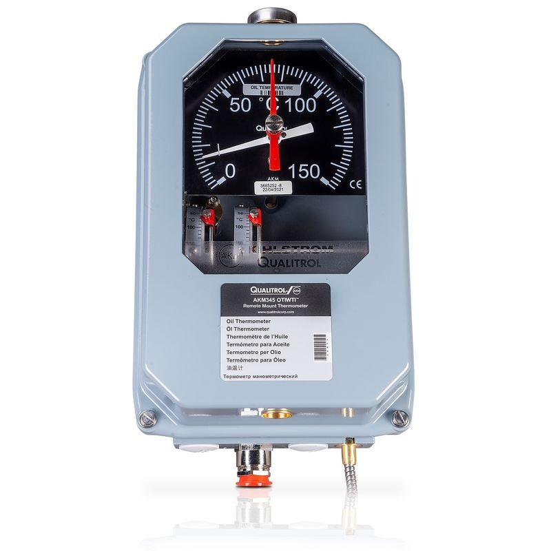
Oil Temperature Indicators are used to monitor the temperature of the insulating oil within the transformer's tank. It is crucial for observing overheating of the transformer's insulating oil. High oil temperatures can result from factors such as load variations, ambient temperature changes, and internal faults. Monitoring oil temperature helps manage the transformer's cooling system. Cooling mechanisms, such as fans, can be activated if the oil temperature exceeds safe limits. By monitoring oil temperature trends over time, maintenance personnel can identify potential issues and schedule maintenance activities proactively. Monitoring oil temperature also contributes to maintaining the quality of the insulating oil. Elevated temperatures can accelerate oil degradation, leading to reduced insulating properties.
This capillary-based, mechanical, remote-indicating thermometer features configurations for oil temperature measurement with up to 6 flexible switches for alarm, trip, and cooling system functions. Maintaining proper oil temperature ensures the optimal performance and reliability of the transformer in various operating conditions.
Flexible for most control and alarm systems with 6-switch capability
260° dial deflection for ease of observation and interpretation
Enclosures with IP55 or IP65 rating with numerous mounting configurations available, including extreme temperatures down to -60°C
Overheating detection
Cooling system management
Predictive maintenance
Oil quality maintenance
Optimal transformer operation
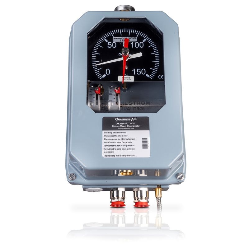
Winding Temperature Indicator (WTI)
Winding Temperature Indicators are critical devices used in power and distribution transformers to monitor and indicate the temperature of the transformer windings, which are the major conductive components carrying current. Unlike oil temperature indicators, which monitor the oil surrounding the windings, WTIs measure the actual winding temperature, which tends to run hotter than the oil. This gives a more accurate picture of transformer load stress and its proximity to thermal limits.
Heat is generated during operation due to the flow of electrical current through a transformer's windings. Accurate temperature monitoring contributes to effective asset management by optimising maintenance schedules and extending transformer lifespans. Winding temperature indicators are designed to activate alarms or trips if temperatures exceed safe limits. They could provide input to cooling systems (like fans or pumps) to maintain safe operating temperatures, and some advanced models can record historical temperature data for trending and diagnostics.
6-switch capability with adjustable hysteresis
260°-dial deflection for ease of observation
High switching capability no extra components for fan bank control and alarm trip
Various analogue outputs available (mA, Pt 100, and Cu 10)
Enclosures with IP55 or IP65 rating with numerous mounting configurations available, including extreme temperatures down to -60°C
Monitoring and protection
Asset Management
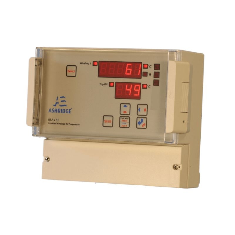
Ashridge WTI and OTI
The Ashridge 852 WTI & OTI provides an ultra-precise reading by continuously measuring the winding temperature and the oil temperature and displaying the data on a dual display. Top oil temperature measurements and the winding current are combined with Ashridge's algorithm, which is based on the IEC 354 standard, to provide accurate temperature readings. The extensive range includes alarm relay output, data logging, a wide range of CT inputs, dual display and an intelligent cooling control system with ‘deviation from normal’ alarms to ensure optimal asset life and protection for the transformer.
For accurate temperature readings and data logging, the Ashridge software provides a "compare settings with template" facility and downloads the settings for incorporation into documentation or archiving. Understanding the transformer lifespan and regularly examining the temperature increase the safety of the transformer and the personnel working on it. Proper temperature monitoring contributes to effective asset management by optimising maintenance schedules and extending the lifespan of transformers.
National Grid approved: Category ‘A’ unrestricted as WTI
The 852-113 logs top oil and hot spot temperatures every 30 minutes, as well as peak temperatures, system entries and power cycling
SCADA outputs of Modbus RTU and DNP 3.0
Direct CT input connection reduceing cabling requirements
Multiple relay outputs: Control, alarm and trip functions, including an output provided for Internal system watchdog alarm
Designed for easy installation using a wide range switch-mode power supply allows the device to be connected to a variety of input voltages automatically
Long life and validated reliability by providing an indication of transformer lifespan
Monitoring and protection of power and distribution transformers
Renewable energy transformers
Battery storage transformers
Industrial transformers
Urban and residential transformers
Grid transformers
Remote transformer installations
Data centre transformers
Asset management
Bunds and Filters
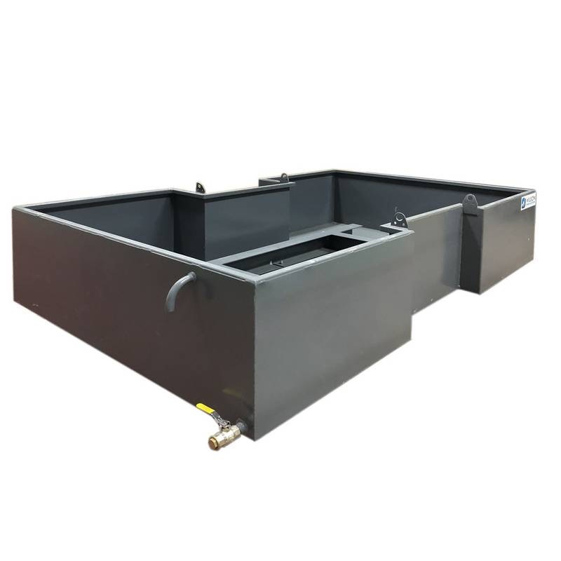
A bund, also known as a containment pit or catchment area, is a secondary containment system designed to contain and prevent the spread of oil in case of a leak, spill, or rupture of transformer radiators, main tank or other components. The bund is constructed around the transformer and is designed to hold 110% of the total liquid in the transformer, ensuring that any leaks or spills are prevented from reaching the surrounding environment.
The primary purpose of the bund is to contain oil leaks, preventing environmental contamination or hazards. Bunds are critical for preventing oil spills from reaching the soil and water, reducing the potential harm to ecosystems and groundwater. Compliance with environmental regulations and standards is a key application of bunds. Bund mitigates the financial and legal risks associated with environmental pollution resulting from oil leaks or spills.
Bund filters are designed to capture hydrocarbon pollutants while letting clean rainwater pass through and safely discharge into the environment. By stopping bunds from filling up and spilling over, they reduce the need for costly oil-water separators or vacuum tanker services.
110% capacity: Designed to hold the entire transformer’s liquid contents, mitigating leaks and spillages further
Bunds limit the spread of fire by containing flammable fluids within a defined area
Help meet environmental and safety regulations (e.g., EA, ISO, local authorities)
Filters offer a low-maintenance, low-cost and easy-to-install drainage for bunds
Filters eliminate hydrocarbons to undetectable levels by using advanced polymers that chemically bind and neutralise oil
Filters automatically shut off once full capacity is reached
Leak and spill containment
Environmental protection
Compliance with regulations
Mitigating risks
Anti-Vibration Pads
Anti-Vibration Pads are positioned beneath the transformer to reduce or eliminate the transmission of vibrations from the transformer to the surrounding structure. These pads are made from materials like rubber, neoprene, or composite materials that can absorb and dampen vibrations, protecting both the transformer and the surrounding infrastructure whilst reducing noise. Minimising vibrations can increase the lifespan of transformers and other equipment as a result of the reduced wear and tear caused by mechanical stresses.
Anti-Vibration Pads are soft, elastic materials that act as a buffer between the transformer and its foundation or supporting structure. Power transformers and medium to large distribution transformers can generate significant vibrations due to electrical activity, mechanical movement, and cooling processes (such as the operation of fans or pumps). They can benefit from Anti-Vibration Pads as noise and vibrations are dampened that might otherwise be felt by nearby residents or occupants. In environments where sensitive equipment or precision instruments are located near transformers, such as in hospitals or research facilities, anti-vibration pads help prevent vibrations from interfering with the operation of these devices. Transformers located near highways or railway tracks can be subjected to vibrations from passing vehicles or trains. Anti-vibration pads help mitigate the impact of these external vibrations. Vibrations can generate audible noise, especially when they’re transmitted to the building structure. Anti-vibration pads reduce this noise, contributing to a quieter environment.
Reduction of noise pollution, especially in areas where transformers are installed close to inhabited spaces or other sensitive areas
Absorb and dampen vibrations caused by the operation of transformers, preventing vibrations from spreading to the building structure and other equipment
Distribute the weight of the transformer evenly across their surface. This helps prevent point loading and ensures uniformal support of the weight of the transformer
Reduces the risk of damage to transformer foundation and surrounding electrical equipment, such as electrical connections, insulation, and transformer bushings
Extending transformer's operational life by reducing mechanical stress of the transformer and its components
Power Transformers
Distribution Transformers
Sensitive environments
Highway and rail installations
Noise reduction
Longevity of equipment
Conservator
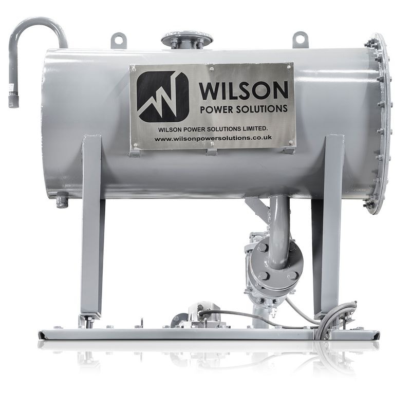
The conservator helps manage the expansion and contraction of insulating oil due to temperature changes. This is important for ensuring proper cooling and insulation properties of the transformer. Conservators prevent overpressure from building up inside the transformer, which could result in mechanical stress or damage to components.
As gases are generated within the transformer due to normal operation or faults, the conservator allows these gases to escape safely, preventing pressure build-up. The conservator reduces oil surface contact from surrounding air, thus minimising the ingress of moisture or contaminants. By providing space for oil expansion and contraction, the conservator minimises exposure to air, reducing the risk of oil oxidation.
Provides extra space for transformer oil to expand and contract as temperatures rise or fall
Prevents internal pressure build-up that could damage the transformer
Fitted with a breather system (ie. silica gel breather) to prevent moisture and contaminants from entering the oil
Equipped with a oil level indicator or gauge glass to allows operators to monitor the oil level inside the conservator to help detect leaks or oil loss
If fitted with an aircell (bladder or diaphragm), it physically separates the transformer oil from ambient air, preventing moisture, oxygen, and airborne contaminants from degrading the oil
Aircell maintains drier and more stable oil, reducing the risk of acid formation, oxidation, and sludge buildup
Aircell allows for longer intervals between oil tests, breather changes, or oil treatments with fewer chances of internal corrosion or moisture ingress
Aircell maintains stable oil conditions which lowers the risk of insulation failure or internal arcing
Oil level maintenance
Preventing overpressure
Expulsion of gases
Preventing oxidation
Buchholz Relay
Oil- and gas-actuated protection relays are used on liquid-insulated transformers to provide protection from electrical faults occurring inside the transformer, accompanied by gas generation or oil surge onto the conservator. The Buchholz relay is primarily designed to detect the presence of gases generated due to electrical faults, such as short circuits or insulation breakdown, occurring within the transformer.
The primary application of a Buchholz relay is to detect internal faults within the transformer, such as short circuits between windings, inter-turn faults, or arcing. Rapid gas generation within the transformer's insulating oil can indicate insulation degradation, overheating, or other issues, providing early warning of potential problems. The presence of gas can indicate the occurrence of faults within the transformer. Buchholz relays help detect these conditions. Early detection of internal faults by the relay helps prevent major failures that could lead to costly downtime and extensive repairs. By analysing the composition of the gases collected by the Buchholz relay, maintenance personnel can gain insights into the nature of the fault and the transformer's condition.
The Buchholz relay's Gas Collecting Device is a small chamber with three functions: extracting gas from the Buchholz relay and venting it from the system, testing both the alarm and trip circuits of the Buchholz relay, and draining oil from the Buchholz relay.
Detect the presence of gases in the insulating oil of the transformer as a result of arcing, overheating, or other internal faults
Gases generated within the oil rise to the top of the transformer and accumulate in a chamber calleed Gas Collecting Device
Float mechanism in the Gas Collecting Device to respond to the accumulation of gas due to the pressure exerted by the gas
The movement of the float activates switches or contacts that trigger alarms, trips, or other protective and isolation actions from the power system
Relays comply with environmental conditions as classified in EN60721-3-4, such as a vertical shock of 100m/s2 and stationary sinusoidal vibration class 4M4
Internal fault detection
Arcing detection
Preventing catastrophic failures
Gas and oil movement detection
Enhancing the safety of transformers
Large oil-filled power transformers
Medium to large scale distribution transformers
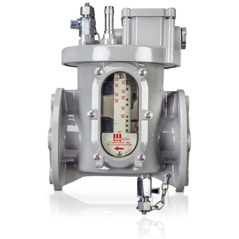
Oil Surge Relay
An Oil Surge Relay is a protective device designed to detect sudden or abnormal changes in the oil level or pressure inside the transformer, especially around the tap changer. The tap changer is a crucial component of the transformer that adjusts the voltage ratio by selecting different taps on the transformer windings.
The oil surge relay is designed to safeguard the on-load tap-changer and transformer in the event of a fault occurring within the tap-changer or selector switch oil compartment. It activates by tripping when the oil flow rate between the tap-changer head and the conservator surpasses a predetermined threshold.
Detects abnormal surges or drops in oil pressure and level during the tap changer's operation
Triggers an alarm or trip signal if abnormal oil conditions are detected, providing early warnings or automatically isolating the transformer
Helps prevent insulation failure or other damage by ensuring oil remains within the required levels and pressure
Monitors for issues like leaks or mechanical faults in the tap changer that could affect the transformer’s oil system
Ensures the transformer’s oil system is stable, during tap changer operation, preventing uneven oil flow or pressure variations
On-Load Tap Changer Protection
Internal Fault Detection
Transformer Oil System Protection
Enhanced Transformer Longevity
Voltage Regulation Systems
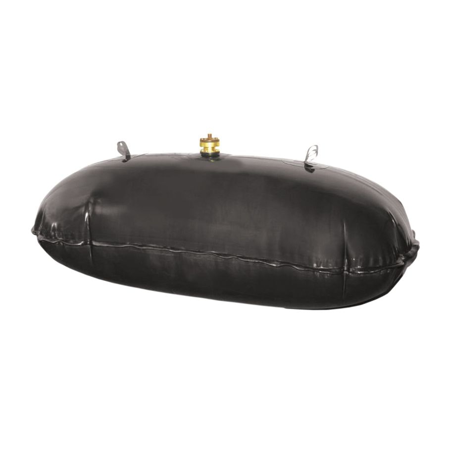
Aircell & Rupture Relay
An aircell is a flexible diaphragm or rubber bag within the transformer's conservator that holds air. Its primary function is to provide a space for the transformer’s oil to expand and contract as the temperature changes without letting it come into contact with the outside atmospheric air, which can introduce moisture and oxygen, degrading the oil. The Aircell expands or contracts by absorbing or releasing air, as the oil level changes due to temperature. By allowing for oil expansion and contraction, the Aircell helps maintain a steady internal pressure, preventing tank or conservator damage due to pressure changes.
A rupture relay is a safety device used in transformers to monitor the integrity of the transformer’s oil system, particularly in relation to the Aircell. If the Aircell fails or the oil pressure reaches dangerous levels, it can cause the rupture of the conservator or other components. The rupture relay acts as a safeguard, detecting any sudden and excessive pressure increase within the transformer’s oil system. If the pressure exceeds safe levels, the rupture relay activates, either signalling an alarm or automatically triggering the transformer to shut down to avoid damage or catastrophic failure.
Absorbs or releases air to respond to expansion of oil during temperature changes to prevent pressure buildup
Keeps the oil separate from the atmospheric air, maintaining the oil's insulating properties
Monitors the pressure levels within the transformer’s oil system
Triggers an alarm or shuts down the transformer if the pressure exceeds safe limits, preventing rupture or damage
Helps detect and prevent critical failures like Aircell rupture or oil leakage
Sensitive Surrounding Environments
Transformer Oil System Protection
Maintaining Oil Quality in Power Transformers
High Voltage Applications
Safety in Industrial and Utility Installations
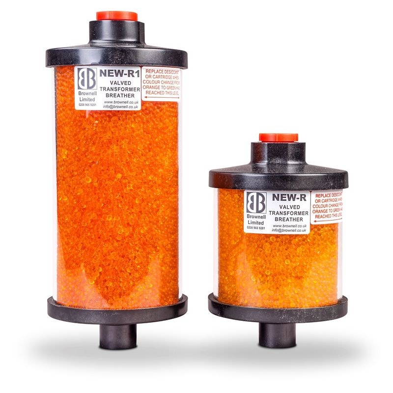
Transformer Breather
Offering protection against high humidity, pressure variations, dielectric loss, and outgassing, the Brownell Transformer Breather absorbs moisture from the air, maintaining dryness. It features a shatterproof, UV-stabilised polycarbonate cylinder. The Envirogel Orange to Green colour-changing silica gel allows for visual recognition when the unit needs replacing or refilling.
The primary purpose of a transformer breather is to control the moisture levels in the conservator tank and the insulating oil. Moisture can lead to oxidation or degrade the oil's insulating properties and cause insulation breakdown. The breather's air filter prevents dust, dirt, and other contaminants from entering the tank and contaminating the oil. Transformer breathers ensure the tank remains at atmospheric pressure by allowing air movement. This prevents overpressure occurrences that could damage the transformer. Monitoring the colour indicator of the breather allows service personnel to schedule maintenance and desiccant replacement when needed.
The device contains a desiccant silica gel, that absorbs moisture from the air entering the conservator tank. This helps maintain the dryness of the insulating oil
Robust manufacture of the UV-stabilised polycarbonate cylinder allows for an accurate reading and consistency
The Envirogel Orange to Green colour changing silica gel visually indicates when the unit needs replacing or refilling
The silica gel inside the breather helps control the humidity level within the conservator tank, preventing the formation of moisture that can lead to issues such as insulation breakdown and sludging of oil
Two-way, low-pressure valves fitted in the base of the breather ensure that atmospheric air enters the desiccant charge when a negative pressure differential occurs within the transformer
Moisture control
Preventing contamination
Minimising oxidation
Conservator protection
Predictive maintenance
Pressure Vacuum Gauge (PVG)
Pressure and/or vacuum indicator for accurate representation of the pressure state inside the transformer, featuring a 3.5-inch (88.9 mm) dial with at least 180° of angular pointer deflection for easy reading at a glance and available in a wide variety of pressure ranges and scales for many applications.
PVGs play a vital role in assessing a transformer's overall health. Abnormal pressure or vacuum readings could indicate internal issues such as partial discharges, winding faults, or oil degradation. Monitoring pressure and vacuum levels helps prevent catastrophic failures. Overpressure situations could lead to oil leaks, insulation breakdown, or even explosions, while excessive vacuum could cause moisture and contaminants to enter the transformer.
By analysing pressure and vacuum trends over time, maintenance professionals can predict when a transformer might require maintenance. This approach can help avoid unplanned downtime and reduce operational costs. Pressure and vacuum monitoring contribute to the safety of the transformer and the personnel working around it. Early detection of abnormal conditions allows for timely actions. Maintaining proper pressure and vacuum levels ensures the transformer operates within its designed parameters, optimising its efficiency and lifespan.
Internal pressure measurement with an accuracy of ±3% of full scale
Measuring the vacuum level within the transformer, created due to temperature fluctuations
Durable design for harsh environments with corrosion resistant materials
Standard dial range of -10 to +10 psi
Pressure bleeder and volt free contact options are available
Pressure or vacuum indication
Transformer health monitoring
Preventing failures
Predictive maintenance
Performance optimisation
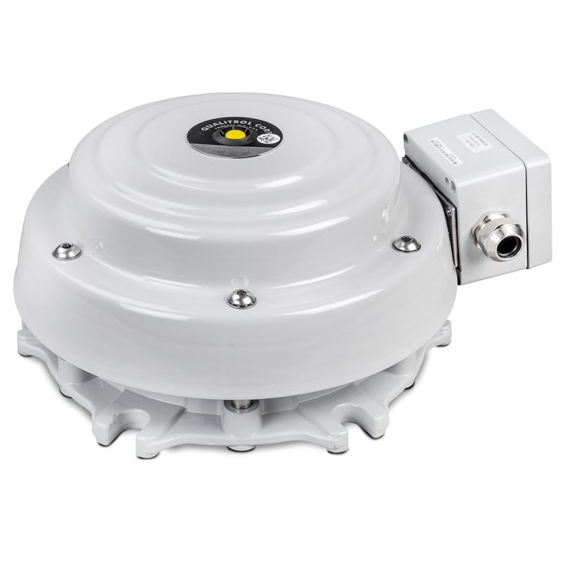
Pressure Relief Device (PRD)
Mechanical overpressure protection device provides pressure-relief on transformers during overpressure conditions, automatically resealing once pressure has subsided. PRDs are designed to release excess pressure in a controlled manner to avoid transformer tank rupture or other potential hazards.
The primary purpose of a PRD is to prevent the buildup of excessive pressure within the transformer tank. Excessive pressure can be caused by events such as internal electrical faults, short circuits, and rapid heating. By releasing pressure in a controlled manner, PRDs prevent the transformer tank from rupturing due to overpressure, which could result in oil spills, fires, or, in severe cases, explosions.
PRD helps avoid the ejection of insulating oil from the transformer tank, which can occur if pressure is not relieved properly. Oil ejection poses safety risks and can cause environmental damage. PRDs can be manually activated during maintenance or emergency situations to release pressure from the transformer.
Quick response time and automatically reseals after pressure has subsided
Device reseals at no less than half of its normal operating pressure
Redirects flow of hot oil and gas away from personnel or critical parts on the transformer
Operating pressure is adjustable in three ranges (2.9 to 5.7 psi, 5.8 to 8.6 psi and 8.7 to 11.6 psi)
Corrosion resistant materials for extreme conditions
Can be specified with up to two alarm switches (with 4 contacts) that activate upon valve operation
The indicator and optional alarms will trip as the mechanism actuates
Mesh flow opening allows for quick pressure relief, protecting your equipment while limiting the possibility of debris entering the device
Overpressure protection
Protection against tank rupture
Preventing oil ejection
Emergency Release
Load tap changers
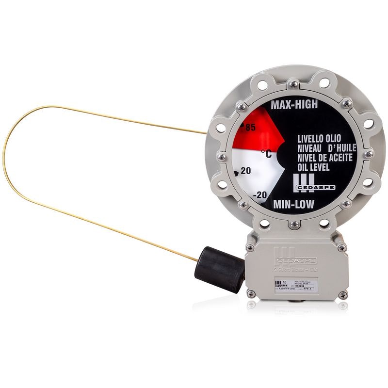
Magnetic Oil Gauge (MOG)
Magnetic Oil Level Gauge is used to measure the level of insulating oil within the transformer tank. Specifically designed for use on power transformers, this device gives an analogue indication of the oil level inside the conservator by a graduated dial with arrow and one or more electric signals when the oil inside the conservator reaches the maximum or minimum level.
The primary purpose of the MOG is to monitor the oil level within the transformer tank. Adequate oil levels are crucial for proper cooling and insulation. Low oil levels can lead to overheating, reduced insulation effectiveness, and potential damage to the transformer. Consistent monitoring of oil levels over time can help predict potential maintenance needs. Significant changes in oil levels indicate leaks or other issues requiring attention. MOGs assist in maintaining the integrity of the transformer's containment system.
Monitor the oil level inside the transformert to help operators visually assess whether the oil level is within the safe operating range
Magnetic float that rises and falls with the oil level inside the transformer tank
The float is connected to an indicator on the exterior of the tank
The indicating system is located Inside the body and is composed by a yellow arrow, a graduated scale, one or more contacts activated by cams and a permanent magnet
Passive device that does not require an external power source. They rely on the interaction between the magnetic float inside the tank and the indicator outside
The device design is reliable as it comprises of a robust yet compact aluminium alloy casting, along with a terminal box. Both are waterproof to prevent oil to seep through. This also ensures a longer lifespan and resistance to corrosion
Oil level monitoring
Predictive maintenance
Power and distribution transformers
Forced Fan Cooling
Additional cooling mechanisms are sometimes required in transformers to dissipate excess heat generated during their operation. Transformers generate heat due to core losses, winding resistance, and other factors. Proper cooling methods, such as Forced-Fan Cooling (ONAF), maintain their efficiency and prevent damage from overheating.
Power Transformers used in electrical substations and distribution networks can generate significant heat due to the high voltages and currents they handle. Forced-fan cooling is commonly used in these transformers to ensure efficient operation and prevent overheating. Transformers used in industrial settings, such as manufacturing plants and large facilities, often require forced fan cooling to handle the heat generated by heavy loads and continuous operation. Transformers that experience varying load conditions or operate under heavy loads periodically may use forced fan cooling to maintain stable temperatures during peak demand. Transformers located in areas with high ambient temperatures or limited ventilation can greatly benefit from forced-fan cooling to ensure consistent performance.
Maintain the transformer’s operating temperature within safe limits
Reducing the likelihood of thermal runaway and help avoiding core or winding damage
Enableing transformers to run at higher efficiency, reducing the losses due to heat and ensuring optimal performance under varying loads
Enhancing heat dissipation capacity in larger transformers or those operating under heavy load, by increasing airflow across the heat-exchanging surfaces
Maintaining lower operating temperatures reduces the risk of insulation degradation and oil breakdown, prolonging the transformer’s lifespan
Power Transformers
Battery Storage Grid Transformers
Solar Photovoltaic Transformers
Industrial Transformers
High-load conditions
Harsh environments
Forced Air Cooling (ONAF)
Forced Oil and Air Cooling (OFAF)
Continuous Maximum Rating (CMR)
Continuous Emergency Rating (CER)
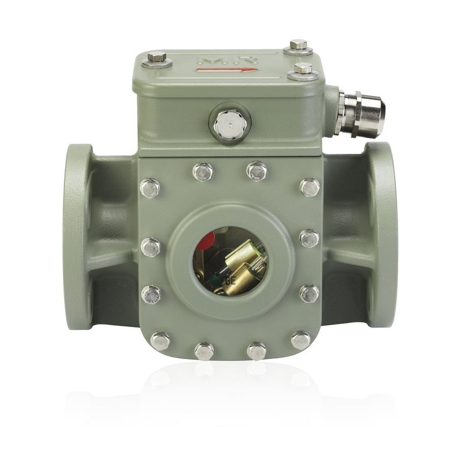
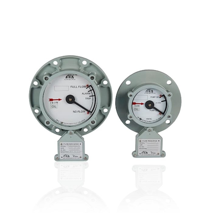
Oil Flow Indicator & Pumps
An oil flow indicator is a device used to monitor and display the movement of oil within the transformer. It helps operators ensure that oil flows properly through the cooling system, which is crucial for maintaining transformer performance and preventing overheating. The indicator provides a visual or mechanical signal if there is a problem, such as low oil flow, which a pump failure or oil blockage could cause. Oil Flow Indicators provide a clear, real-time indication of whether oil flows correctly through the system. Detecting abnormal oil flow conditions helps prevent overheating and protects the transformer’s insulation from damage.
The Oil Pumps in a transformer are responsible for circulating the oil through the transformer’s core and coils to transfer heat away from the transformer’s active parts. This helps maintain the temperature of the transformer within safe operational limits, preventing overheating that could damage the insulation or other internal components. They ensure that the oil flows through the transformer, maintaining consistent cooling of the internal components. Therefore, they help stabilise the transformer’s temperature by dissipating heat generated by the electrical load. Proper cooling via oil circulation prolongs the life of the transformer’s insulation and other components. In some designs, pumps are also used to maintain adequate pressure levels in the oil system.
Provides real-time monitoring of oil flow within the system
Identifies issues such as pump failure or reduced flow, allowing for early intervention
Alerts operators to potential risks of overheating, helping to safeguard the transformer
Keeps oil circulating throughout the transformer to ensure effective cooling
Maintains safe operating temperatures by efficiently dissipating heat
Reduces the risk of overheating, which can damage the transformer
Transformer Cooling Systems
Prevention of Overheating
Fault Detection and Protection
Utility and Industrial Applications
On-Load Tap-Changer (OLTC)
An OLTC maximises energy savings by maintaining a consistent secondary voltage despite variations in input voltage and load conditions. Achieved by adjusting the turns ratio of a transformer’s windings whilst the transformer is energised and in operation, OLTC can perform up to 500,000 maintenance-free operations, outliving the transformer.
OLTCs are primarily used to regulate the output voltage of a transformer to maintain a steady voltage level at the load terminals. This is important for delivering consistent and reliable power to consumers. As the electrical load on the transformer fluctuates, the OLTC ensures that the output voltage remains within the pre-defined voltage range. This is particularly important in distribution networks with varying load demands or fluctuating voltage supply, causing over- or under-voltage issues. OLTCs can reduce the voltage to prevent transformer overloading during periods of high load. This can help prevent overheating and extend the transformer’s operational life.
OLTCs can change tap positions while the transformer is in operation, unlike DETC. This capability minimises downtime and interruptions to power supply
Maintaining a constant secondary voltage by compensating for fluctuations in the input voltage or load changes
Voltage regulation for power and distribution transformers
Load changes
Grid voltage variations
Avoiding overloads
Built for renewables
Reliability of the power supply
Extra energy savings
Reduction of voltage sag and swell events
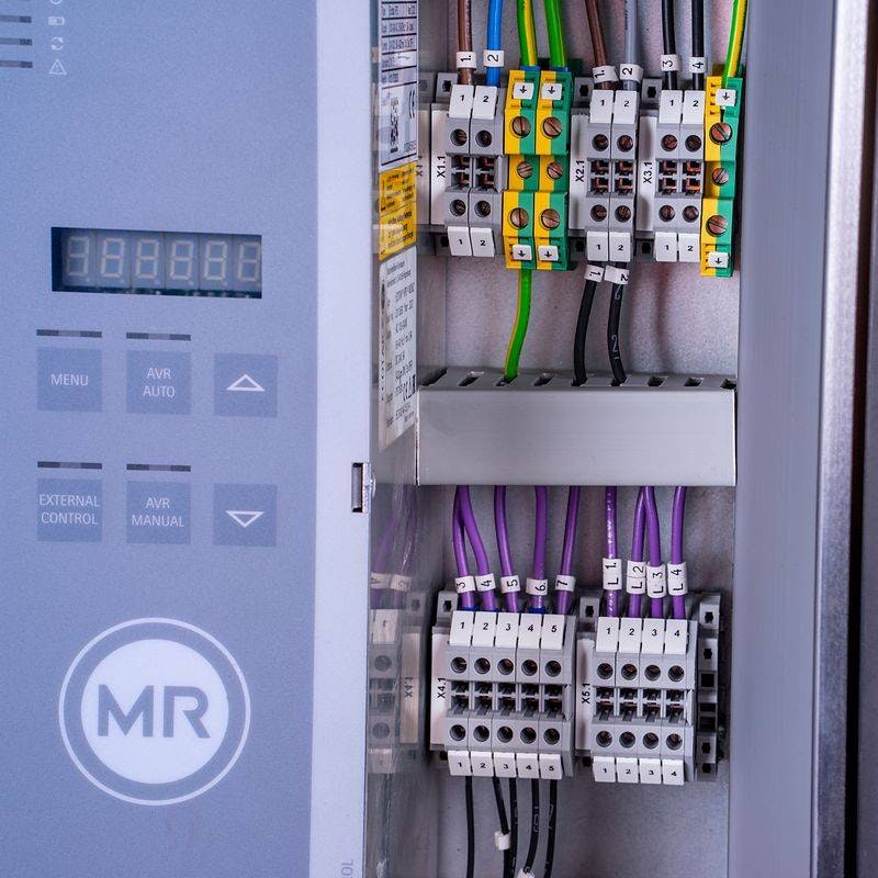
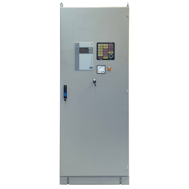
AVR Relay
The Automatic Voltage Regulation (AVR) Relay is used in conjunction with on-load tap changers (OLTC) on Power Transformers to monitor and automatically regulate the transformer's output voltage. It plays a crucial role in maintaining the voltage within a pre-defined range and preventing voltage-related issues that could affect the performance of the transformer and connected equipment.
AVR Relays are critical for maintaining a stable power supply and preventing voltage fluctuations that could damage equipment or disrupt operations. AVR relays help ensure the voltage remains within acceptable limits despite load or unstable supply and fluctuations. They can quickly respond to sudden voltage surges or dips caused by faults or disturbances in the power grid and adjust the tap settings to bring the voltage back to specified levels. In remote substations or substations that are part of a larger network, AVR relays provide a means of automatic response, enhancing the efficiency of voltage regulation.
Continuous monitoring of the output voltage of the transformer and comparing it to preset reference values
If the measured voltage deviates from the desired range, the AVR relay triggers corrective actions to regulate the voltage by adjusting the tap settings of the transformer’s on-load tap changer (OLTC)
If the voltage goes beyond certain limits, indicating a potentially serious issue, the AVR relay can activate alarms and initiate tripping sequences to protect the transformer and the connected network
Advanced AVR relays can communicate with supervisory control and data acquisition (SCADA) systems or other monitoring devices to enable remote monitoring, control, and data logging
Voltage regulation
Load fluctuations
System stability
Preventing overvoltage and undervoltage
Remote monitoring and control
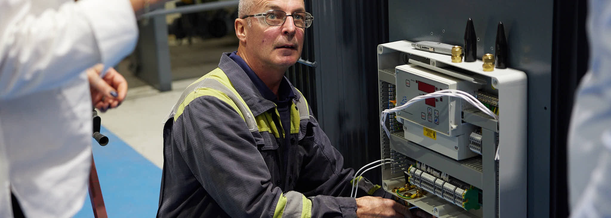
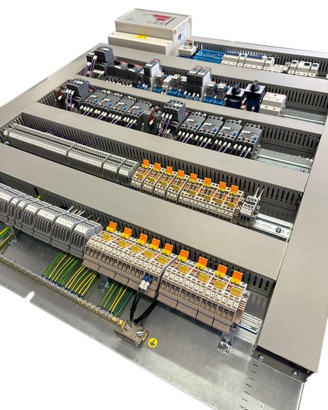
Marshalling Box
Marshalling boxes serve as a central point for organising and connecting various electrical cables and wires associated with different components of the system. They play a crucial role in maintaining a clean and organised wiring arrangement, facilitating maintenance, and ensuring an organised arrangement to avoid errors.
Designed by our engineers and assembled in our "bungalow" in Leeds, marshalling boxes organise the wiring and connections between the transformer and the necessary monitoring and protection systems, including connections to temperature sensors, pressure sensors, and protection devices. In systems where multiple cables from different sources need to be interconnected, such as in complex transformer installations, marshalling boxes simplify the wiring arrangement, making it more manageable and efficient.
Offering protection to the internal wiring and components from environmental factors and potential physical damage
Various termination points or terminals where cables and wires from different sources are connected. These terminals are organised to correspond to specific components, sensors, instruments, or other elements of the system
Clear and standardised labelling to enable technicians to identify and troubleshoot connections accurately, reducing the risk of errors
Cable glands, cable ties, and cable trays to route and secure cables neatly within the box, preventing tangling and ensuring easy access
Can be mounted in a range of configurations to suit the necessary application of your transformer
Systems connection management
Wiring management and organisation
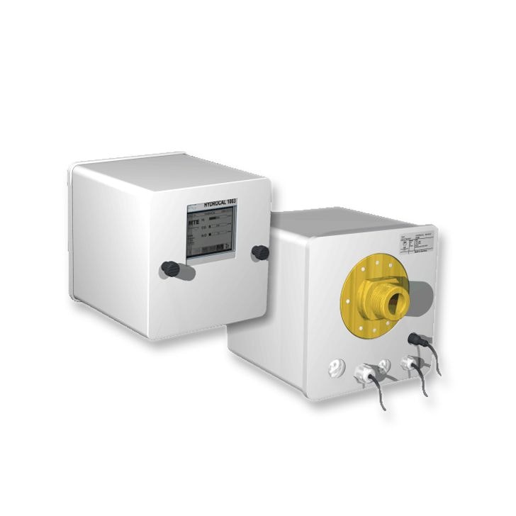
Dissolved Gas Analysis (DGA)
Dissolved Gas Analysis (DGA) Hydrocol 1003 is a critical diagnostic device used to monitor the health and condition of the transformer’s insulation oil. DGA continuously analyses the gases dissolved in the oil, which can indicate the presence of faults or degradation in the transformer. The gases that are dissolved in the oil can form as a result of electrical discharges, overheating, or arcing within the transformer. By detecting and analysing these gases, the Hydrocol 1003 helps identify potential issues early on, enabling preventive maintenance and reducing the risk of catastrophic transformer failure. These gases are produced due to various fault mechanisms, including overheating, which can generate gases such as hydrogen (H₂) and carbon monoxide (CO). Faults such as Partial Discharges or Arcing can create gases like acetylene (C₂H₂) and methane (CH₄). Faults such as degradation of the transformer’s paper insulation (Cellulose Breakdown) can generate gases like carbon dioxide (CO₂) and carbon monoxide (CO).
DGA analyses the concentration of these gases and compares the results with established fault patterns. A high concentration of certain gases or the presence of specific gas combinations can indicate problems. DGA can be connected to an online platform (SCADA) where real-time data can be analysed, and alerts can be sent to operators or maintenance personnel. HYDROCAL 1003 would allow operators to track the transformer's condition remotely, receive diagnostic data, and anticipate failures before they occur.
Capable of detecting a wide range of gases that are indicative of different transformer faults
Provides real-time analysis and alerts, enabling rapid response to potential faults or issues
Acts as an early warning system, detecting problems before they can cause significant damage
Can be integrated with SCADA systems, allowing for remote monitoring and control
Operates continuously or be used for periodic sampling, depending on the application and the level of monitoring required
Fault Detection and Diagnosis for overheating, partial discharge, arcing or electrical discharges and cellulose degradation
This website uses cookies. Please refer to our
Cookie Policy
to see how they are used. By clicking accept you consent to the use
of cookies on this website.